Introduction
This is going to be a crash course in functional testing. It is not going to be an in-depth academic exposition. We're going to be covering nomenclature, definitions and theory.
What is a system?
A system can be thought of as a self-contained set of things working together as parts of a mechanism. We can think of a system abstractly as black box with stuff going on inside that can additionally either have inputs and outputs or not.Think of a car, human, laptop or integrated circuit. Each of these things are systems with clear boundaries and some form of inputs and outputs. A laptop has a keyboard and trackpad as inputs and a screen and speakers as its outputs. An integrated circuit has physical pins as inputs and outputs. Each of them can be considered a self-contained system. Of course they are really systems of systems (e.g., humans made of cells, chips made of transistors), but we can more-or-less arbitrarily set the boundary of the system anywhere we want and treat it as a black box. I don't want to get too philosophical, so we'll leave it at that.
For the remainder of this document, we'll be focusing on the testing theory of electronic components.
How can we test systems?
For a system to be testable we need two things: controllability and observability.
A system with internal state is controllable if the state can be modified by changing the inputs. A system with internal state is observable if the state can be determined by observing the outputs. In other words, poke it and see how it responds. Poke it the right way and we can detect if something is not right on the inside, i.e., we've found a "fault."
What is a fault?
A fault is the hypothesized cause of a system failure. Fault detection asks if there is a fault. Fault diagnoses asks where the fault happened.
What causes faults?
An integrated circuit die rolls off the fab assembly line, gets packaged and and its pads bonded out to the physical pins of the package. It becomes a self-contained system with power, ground and I/O pins. We power it up and it doesn't work. Why? Here's why:
-
manufacturing defects
- mask misalignment
- improper doping profiles
- metal-to-metal shorts
- transistors stuck open or shorted
-
design errors
- logic errors
- interconnect errors
- layout errors
- electric rule violations
-
physical failures
- overstress of chip at burn-in
- lifetime of device
how do we model faults?
All the above causes can be reduced to the following fault models. Test patterns are then derived from the fault models.
- single stuck-at-1
- single stuck-at-0
- multiple stuck-at-1
- multiple stuck-at-0
- gate delay fault
- path delay fault
How do we find faults?
Simply put, you apply a sequence of input test vectors to a system, or in our case a circuit, you observe the output response and compare the response to a precomputed expected response. If there is a discrepancy, the test failed, otherwise the test passed.
Example
Any input or internal wire in this circuit can be stuck-at-0 or stuck-at-1.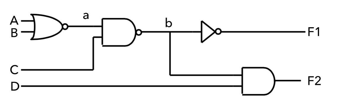
In the example above, if 'b' is stuck high, then regardless of what's inputted to the circuit, F1 will always output low and F2 will always output high when D is high, or low when D is low. From the truth table on the right, we can see that the only inputs that will make 'b' go low are the ones highlighted in green. Thus, these are the only inputs that would uncover the fault. All other inputs would lead to 'b' being high, masking the stuck-at-1 fault.
To correctly test 'b' for a stuck-at-1, a test engineer would come up with a test pattern with either the following test vectors. No additional vectors would be required to test for this particular fault type.
    # Pins A, B, C, D, F1, F2
    V0010HL
    V0011HL
Automatic Test Pattern Generation
There are 4 inputs to the circuit. We could generate a truth table and brute force our way to testing the circuit. However, you'll quickly realize that for non-trivial circuits, as the number of inputs increases, the number of tests needed grows exponentially. This is clearly an untenable approach.
The method used in industry to algorithmically generate test patterns is called ATPG or Automatic Test Pattern Generation. ATPG is used to generate test vectors that can distinguish between correct circuit behavior and faulty circuit behavior caused by defects. The ATPG algorithm reduces to the boolean satisfiability problem (SAT), which falls into the NP-Complete complexity class. ATGP can fail to find tests for faults either because it's intrinsically undetectable or because the algorithm, due to being NP-Complete, doesn't end up finding one. This topic, however, is beyond the scope of this document.
Conclusion
Regardless if test vectors are automatically generated using ATPG or hand-crafted by test engineers, the Gemini Tester platform lets you easily create test patterns using either the Dots vector programming language or the PyGemini Python module.
Please see the dots spec section for more information.
| A | B | C | D | a | b | F1 | F2 |
|---|---|---|---|---|---|---|---|
| 0 | 0 | 0 | 0 | 1 | 1 | 0 | 0 |
| 0 | 0 | 0 | 1 | 1 | 1 | 0 | 1 |
| 0 | 0 | 1 | 0 | 1 | 0 | 1 | 0 |
| 0 | 0 | 1 | 1 | 1 | 0 | 1 | 0 |
| 0 | 1 | 0 | 0 | 0 | 1 | 0 | 0 |
| 0 | 1 | 0 | 1 | 0 | 1 | 0 | 1 |
| 0 | 1 | 1 | 0 | 0 | 1 | 0 | 0 |
| 0 | 1 | 1 | 1 | 0 | 1 | 0 | 1 |
| 1 | 0 | 0 | 0 | 0 | 1 | 0 | 0 |
| 1 | 0 | 0 | 1 | 0 | 1 | 0 | 1 |
| 1 | 0 | 1 | 0 | 0 | 1 | 0 | 0 |
| 1 | 0 | 1 | 1 | 0 | 1 | 0 | 1 |
| 1 | 1 | 0 | 0 | 0 | 1 | 0 | 0 |
| 1 | 1 | 0 | 1 | 0 | 1 | 0 | 1 |
| 1 | 1 | 1 | 0 | 0 | 1 | 0 | 0 |
| 1 | 1 | 1 | 1 | 0 | 1 | 0 | 1 |